
The AF36 Airflow Measurement System
The purpose of the AF-36 Airflow Measurement System is to determine the aerodynamic area of various components such as gas turbine nozzles, nozzle segments, wheels, combustion liners, and other similar components. Historically the AF-36 has gone through a number of design improvements since it was introduced by August Fleming in 1972. Today’s version is a computerized double blower system that is highly accurate, versatile and durable. Of the more than 130 Air Flow Systems produced, more than 120 are still in service. Fleming & Associates Calibration expects the working life span of a new AF-36 to be at least 15 years.
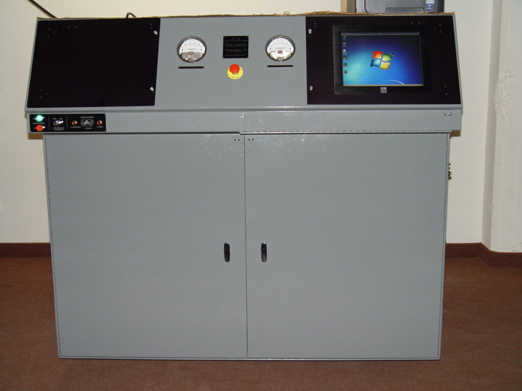
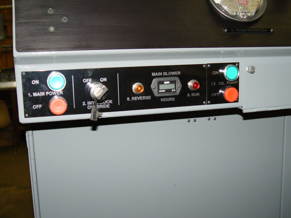
The area is measured dynamically through transfer standards, air pressures, temperatures and blower speeds. This is accomplished by the system adjusting blower speed to obtain the desired differential pressure across the component being measured, and then calculating the area as a function blower speed and the other above measurements. A computerized interface system controller, with Windows XP platform software and a touch screen operator interface control the Airflow Measurement System. Fleming & Associates proprietary software provides the selection of three different pressures across the component: 0.5” (12.7 mm), 1.0” (25.4 mm), and 5.0” (127mm) H2O. The system is calibrated at the factory at these pressures using ASME nozzles (upon request the system may be calibrated and configured to operate at other pressures). The main blower system consists of a positive displacement blower and an AC motor speed control. The main blower speed controls the airflow in the main flow system in order to maintain the desired pressure drop during measurement. Since the pressure drop across the test component is constant, area is proportional to flow. In order to calculate area, sensor measurements are collected and processed by the computerized interface system. The sensors include six (6) thermostats, linear zed with a measurement specific linear zing circuit, a differential pressure transducer, an additional transducer to measure atmospheric pressure, and a humidity sensor to warn the operator of excessively high humidity. See below for more on the computerized interface system.
The AF-36 Airflow Measurement System is calibrated using transfer standards and collecting the blower speed, temperatures and pressures associated with the system bringing fixed differential pressure across the transfer standard. After several transfer standards have been measured an assessment is done to determine the blower’s characteristics. The use of Master components is highly recommended. Master components have two functions in the measurement process: they are used to verify the stability of Airflow Measurement System, and they provide compensation in the measurement process.
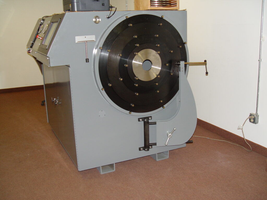
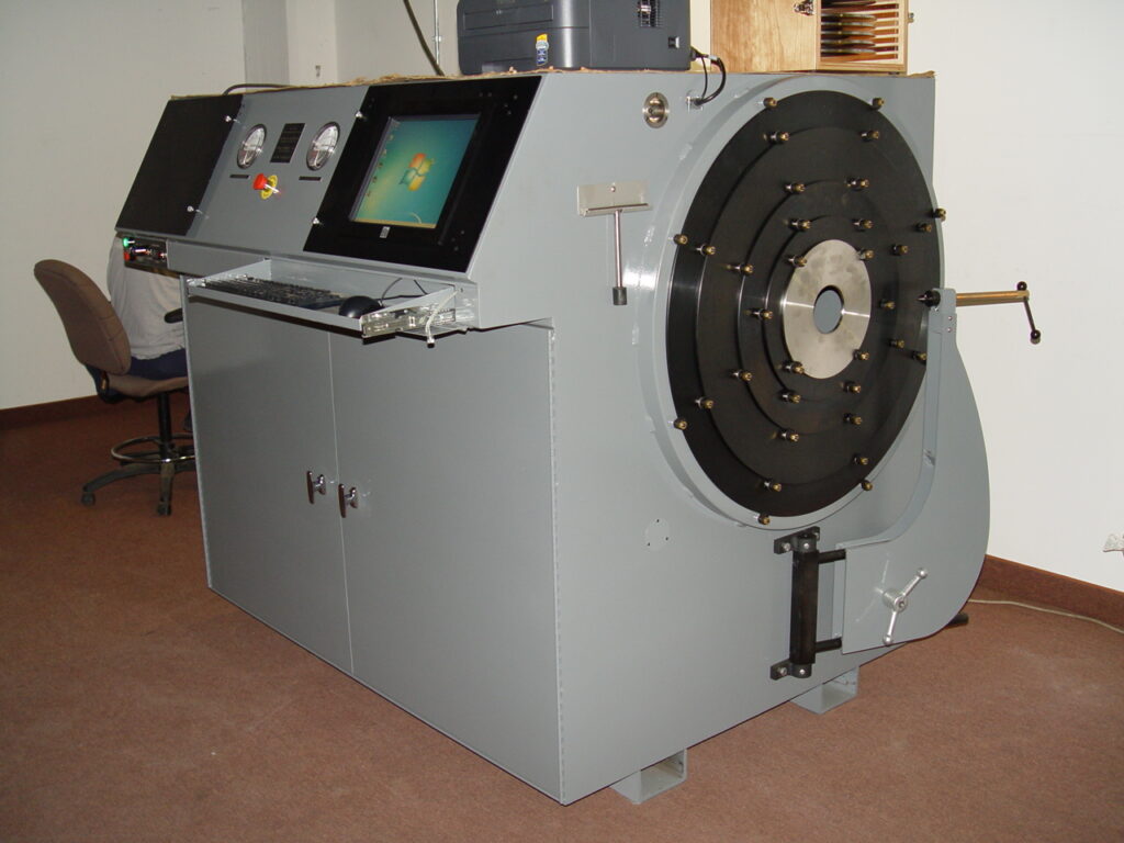
- The AF-36 is a single, self-contained unit that is portable and can be moved with a fork truck; the unit is electrically driven;
- The AF-36 can be operated in both forward and reverse directions. The AF-36’s ability to run in reverse enables easy measurement of combustion liner features. The tooling on some component nozzles is also more readily adaptable to running in the reverse direction;
- The AF-36 cabinet meets NEMA 1 enclosure requirements;
- The AF36 is build to UL (Underwriters Laboratories) and NEC Standards (National Electric Code or NFPA 70) and is CE Compliant (European Union Compliance Standard). Some of the AF36 Airflow Measurement Systems in France and Germany have been UL Certified. UL Certified indicates that the product has been tested by UL to nationally recognized safety and sustainability standards.